Calculators
/Electronics
Half Wave Rectifier Formula & Calculator
Calculate DC output voltage, efficiency, ripple factor, and PIV of a half wave rectifier with formulas, examples, and calculator.
2 min read
Advertisement
Table of Contents
This article compares voltage doublers, voltage triplers, and voltage quadruplers, outlining the differences between these voltage multiplier circuits.
A voltage multiplier is an electronic circuit that takes an AC waveform as input with a peak voltage (Vm) and produces a DC voltage output. The key feature of a voltage multiplier is that the output DC voltage is an integer multiple of the peak AC input voltage (Vm).
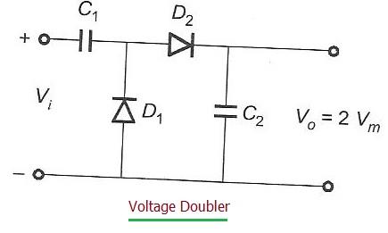
Figure 1 illustrates a typical voltage doubler circuit. As you can see, the input is an AC signal, and the output is a DC voltage. The primary function of this circuit is to approximately double the peak input voltage.
The output DC voltage (Vout) is approximately equal to 2 * Vm, where Vm is the peak voltage of the AC input.
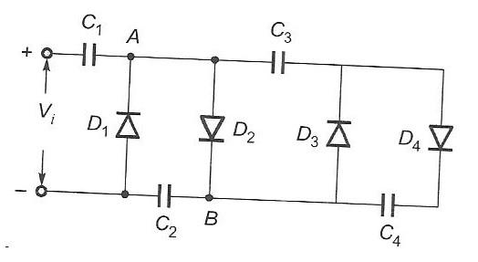
Figure 2 shows the circuits for both a voltage tripler and a voltage quadrupler. These circuits build upon the principles of the voltage doubler to achieve higher output voltages.
In essence, these circuits use a combination of diodes and capacitors to progressively charge the capacitors and achieve the desired multiplication of voltage.
Advertisement
Calculators
/Electronics
Calculate DC output voltage, efficiency, ripple factor, and PIV of a half wave rectifier with formulas, examples, and calculator.
Calculators
/Electronics
Calculate frequency and pulse width of astable and monostable multivibrators using 555 timer formulas with examples and calculator.
Calculators
/Electronics
Calculate efficiency, PIV, ripple factor, and TUF of a center tap full wave rectifier with formulas, examples, and calculator.
Articles
/Electronics
This article explores the advantages and disadvantages of analog multimeters, highlighting their benefits and drawbacks for various applications.
Advertisement
Measurements
/Electronics
Explore the fundamental differences between inductance and capacitance measurements, their related reactances, and the instruments used for measurement.
Articles
/Electronics
Explore the differences between PWM and CCR methods for dimming LEDs, understanding how each technique affects brightness and efficiency.