Measurements
/Electronics
This article covers zener diode testing, essential parameters, measurement techniques, test setups, and common failure modes to help evaluate these components.
3 min read
Advertisement
Table of Contents
This article explores the various test and measurement parameters used to evaluate Silicon Controlled Rectifiers (SCRs), along with the test setups employed for different measurements.
The following parameters of an SCR are typically verified during testing:
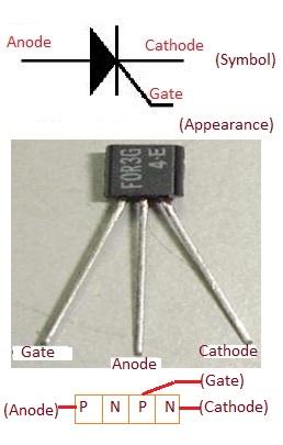
For a better understanding of SCR operation, pin designations, and how to determine if an SCR is functioning correctly, consider watching a relevant YouTube video.
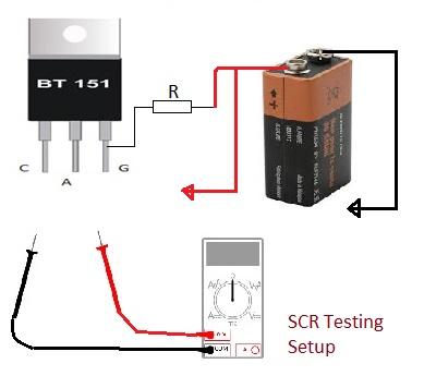
Multimeters are commonly used for SCR testing. SCRs behave similarly to diodes, but they can handle much higher currents. Unlike regular diodes, SCRs need to be triggered into their conducting state. This test aims to determine if an SCR is working correctly. Always refer to the datasheet for the specific SCR part number to identify pin designations.
Advertisement
Related Posts
Measurements
/Electronics
This article covers zener diode testing, essential parameters, measurement techniques, test setups, and common failure modes to help evaluate these components.
Measurements
/Electronics
This article explores the key parameters and testing methods used to evaluate the performance of LEDs, including voltage, current, and light output.
Articles
/Electronics
This article explains how to identify open and shorted zener diodes using resistance and voltage tests with a multimeter.
Equipments
/Electronics
Explore the fundamentals of Bit Error Rate (BER) and Bit Error Rate Testers. Learn about measurement techniques and available equipment.
Advertisement
Equipments
/Electronics
An overview of LED and luminaire test equipment, covering measurements, manufacturers, and key parameters. Essential for ensuring product quality and reliability.
Equipments
/Electrical
Learn the fundamentals of transformer turns ratio, including the governing equation and the use of transformer turns ratio meters for testing. Explore step-up and step-down transformer types.