
Equipments
/RF
Explore the pros and cons of Scalar (SNA) and Vector (VNA) Network Analyzers for transmission and reflection measurements.
3 min read
Advertisement
Table of Contents
This article delves into the fundamental measurements of S-parameters, namely S11, S12, S22, and S21.
A vector signal consists of both amplitude and phase information. When a signal is passed from linear of non-linear device which we call it DUT (Device Under Test) in our discussion; the characteristics of signal will alter. The amplitude/phase of output signal is different compare to input signal. S-parameter convey both of these information i.e. amplitude and phase.
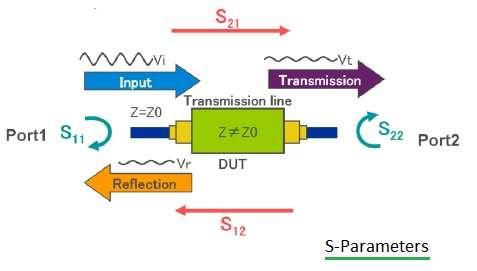
Amplitude variation information provides insertion loss while timing variation provides phase shift. S parameters are complex matrix which helps us analyzing reflection and transmission characteristics in the frequency domain.
It provides information concerning the performance of linear electrical networks, including RF circuits, amplifiers, and filters, whichs includes -
The S-parameter matrix can be used to determine reflection coefficients and transmission gains from both sides of a two port network. This concept can further be used to determine s-parameters of a multi port network.
For a two-port device, there are four S-parameters. The naming convention is “S” followed by two digits. The first digit indicates the output port, and the second indicates the input port. For instance, S21 means the output is measured at Port 2, with the input signal applied at Port 1.
S-parameter measurements can be categorized as:
S11 and S22 provide us information on the following -
S21 and S12 provide us information on the following -
A Vector Network Analyzer (VNA) is the tool used to measure S-parameters. The following figure depicts internal block diagram of VNA.
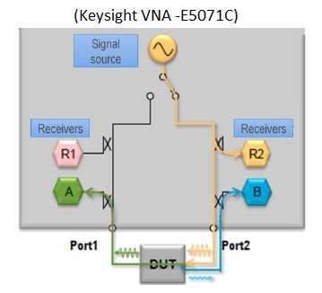
The VNA internally measures both amplitude and phase using four receivers (R1, R2, A, and B).
Here’s how each S-parameter is derived:
In essence, S-parameters give us a complete picture of how a signal behaves when it interacts with a device, which is crucial in RF and microwave engineering.
Advertisement
Related Posts
Equipments
/RF
Explore the pros and cons of Scalar (SNA) and Vector (VNA) Network Analyzers for transmission and reflection measurements.
Terminology
/General
A glossary of common terms used with network analyzers, including transmission coefficient, insertion loss, gain, reflection coefficient, return loss, and S-parameters.
Measurements
/RF
A guide to RF coupler testing, covering key parameters like coupling, directivity, insertion loss, and test setups. Learn how to measure these specifications.
Articles
/RF
A detailed comparison of Scalar and Vector Network Analyzers, outlining their differences in measurement capabilities, hardware, cost, and applications.
Advertisement
Measurements
/RF
This article covers the key test parameters for RF mixers, including conversion loss, noise figure, isolation, and dynamic range. It also describes the test setup.
Measurements
/RF
This article provides a guide to testing RF circulators, covering key parameters, typical test setups, and specifications.