Articles
/General
Analog vs. Digital Oscilloscopes: Key Differences
Explore the fundamental differences between analog and digital oscilloscopes, focusing on their operational principles and display methods.
2 min read
Advertisement
Table of Contents
This article compares voltage doublers, voltage triplers, and voltage quadruplers, outlining the differences between these voltage multiplier circuits.
A voltage multiplier is an electronic circuit that takes an AC waveform as input with a peak voltage (Vm) and produces a DC voltage output. The key feature of a voltage multiplier is that the output DC voltage is an integer multiple of the peak AC input voltage (Vm).
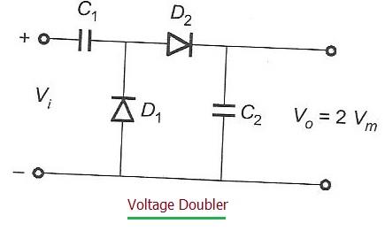
Figure 1 illustrates a typical voltage doubler circuit. As you can see, the input is an AC signal, and the output is a DC voltage. The primary function of this circuit is to approximately double the peak input voltage.
The output DC voltage (Vout) is approximately equal to 2 * Vm, where Vm is the peak voltage of the AC input.
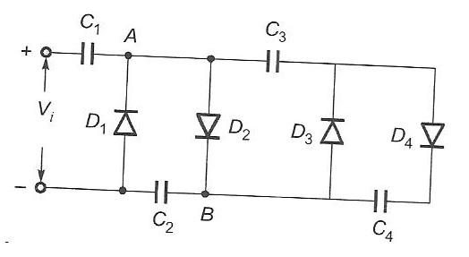
Figure 2 shows the circuits for both a voltage tripler and a voltage quadrupler. These circuits build upon the principles of the voltage doubler to achieve higher output voltages.
In essence, these circuits use a combination of diodes and capacitors to progressively charge the capacitors and achieve the desired multiplication of voltage.
Advertisement
Articles
/General
Explore the fundamental differences between analog and digital oscilloscopes, focusing on their operational principles and display methods.
Measurements
/Electronics
Explore the fundamental differences between inductance and capacitance measurements, their related reactances, and the instruments used for measurement.
Articles
/Electronics
This article explores the pros and cons of analog multimeters, highlighting their benefits and drawbacks for various applications.