Equipments
/Wireless
Understanding MIMO Channel Emulators for Wireless Testing
Explore the functionality and features of MIMO Channel Emulators, focusing on their application in WiFi and LTE testing, particularly the ACE™ MX2 from Azimuth Systems.
3 min read
Advertisement
Table of Contents
This article explores the MIPI RFFE (RF Front End) Interface, comparing versions 1.0 and 2.0 and highlighting their key differences.
The MIPI Alliance maintains and publishes the specifications for the RF Front-End Control Interface (RFFE). They’ve released RFFE versions 1.0, 2.0, and most recently, 2.1. MIPI RFFE provides a standardized way to control various subsystems within an RF system. Think of components like:
This interface is designed to meet the demands of current and future mobile wireless devices.
 Figure 1: A radio receiver using RFFE, DigRF, and eTrak interfaces.
As shown in Figure 1, the RFFE interface plays a crucial role alongside other interfaces like DigRF and eTrak. DigRF is used for communication between the baseband and RFIC in mobile handsets. The eTrak interface is a point-to-point connection between the radio transmitter and the Envelope Tracking Power Supply (ETPS).
RFFE was developed to handle the increasing complexity of front-end requirements, especially with technologies like LTE rel-11, LTE rel-12, and 5G, which utilize multiple Carrier Aggregation (CA) bands and antenna configurations.
The MIPI RFFE interface operates using a point-to-multipoint architecture. It connects a master device to multiple slave devices on a shared bus. Here’s a breakdown of its key features:
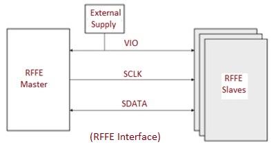
Here are the key specifications of the MIPI RFFE v1.0 interface:
The MIPI RFFE v2.0 interface builds on v1.0 with these enhanced features:
The RFFE interface offers numerous advantages:
MIPI Alliance, Inc. (https://www.mipi.org)
Advertisement
Equipments
/Wireless
Explore the functionality and features of MIMO Channel Emulators, focusing on their application in WiFi and LTE testing, particularly the ACE™ MX2 from Azimuth Systems.
Articles
/Wireless
An in-depth comparison of polarization diversity and angle diversity techniques used to improve signal reception in wireless communications, focusing on their different approaches and applications.
Equipments
/Wireless
A detailed comparison of the R&S CMU200 and CMW500 radio communication test sets, highlighting their key specifications and differences.