Measurements
/RF
RF Circulator Testing: A Guide to Test and Measurement
This article provides a guide to testing RF circulators, covering key parameters, typical test setups, and specifications.
3 min read
Advertisement
Table of Contents
RF isolators play a crucial role in protecting RF components by allowing signal flow in one direction while minimizing reflections and interference. To ensure their efficiency, precise testing and measurement are essential. This article covers the key testing techniques, measurement parameters, and the best equipment used for RF isolator evaluation.
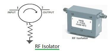
An RF isolator is a two-port device designed to safeguard RF equipment within a system from potential damage caused by reverse power leakage. Think of it as a one-way valve for RF signals. Interestingly, an RF circulator with its third port terminated can also function as an isolator.
When assessing the performance of an RF isolator, several key parameters come into play. Here’s a breakdown of the specifications typically evaluated:
| RF Isolator Specifications | Description |
|---|---|
| Frequency Range | This specifies the range of frequencies over which the RF isolator is designed to operate effectively in a given application. |
| Isolation | This refers to the signal loss from port-2 to port-1, often called reverse isolation. A higher isolation value is desirable, typically falling within the 20-30 dB range. It reflects how well the device prevents reverse signal propagation. |
| Loss or Insertion Loss | This is the signal loss from port-1 to port-2, also known as insertion loss. Lower loss is better. A good RF isolator usually exhibits an insertion loss of less than 1 dB. |
| VSWR or Return Loss | Voltage Standing Wave Ratio (VSWR) should ideally be close to 1. A VSWR close to 1 indicates excellent impedance matching with input and output ports, minimizing signal reflections. |
| Peak Power (Forward & Reverse) | This is the maximum peak power the isolator can handle without sustaining damage, in both forward and reverse directions. |
| Average Power (Forward & Reverse) | This is the maximum average power the isolator can handle without sustaining damage, in both forward and reverse directions. |
The following diagram depicts a typical setup employed for RF isolator testing.
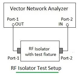
As shown in Figure-2, the setup typically involves a signal source, a network analyzer, and the isolator being tested. The network analyzer is used to measure key parameters like insertion loss, isolation, and VSWR, providing crucial insights into the isolator’s performance.
Proper RF isolator testing enhances system reliability and minimizes signal distortion. By utilizing advanced measurement equipment and techniques, engineers can optimize isolator performance across various RF applications, including telecommunications and radar systems.
Advertisement
Measurements
/RF
This article provides a guide to testing RF circulators, covering key parameters, typical test setups, and specifications.
Measurements
/RF
A guide to RF coupler testing, covering key parameters like coupling, directivity, insertion loss, and test setups. Learn how to measure these specifications.
Equipments
/RF
Explore RF switch specifications, types, and vendors for test setups. Learn about insertion loss, isolation, topologies, and more to make informed decisions.